
Follow Along as We Draw a Complete Motor Control Circuit Using an Electrical Symbol Library
If you’ve ever wondered how professional electrical schematics are created in AutoCAD, this video walks you through the entire process from start to finish.
You’ll learn how to set up your drawing, choose the correct ANSI or IEC electrical symbols, insert components from the Electrical Symbol Library, and complete a simple motor start/stop control circuit.
Whether you’re new to electrical drafting or looking for a faster workflow, this tutorial demonstrates the techniques that electrical designers and CAD professionals use every day.
What You’ll Learn in the Video
During this tutorial, you’ll see how to:
- Choose between ANSI (Imperial) and IEC (Metric) electrical symbol libraries.
- Set up your AutoCAD drawing using the correct title sheet and snap settings.
- Insert electrical symbols from organized pull-down menus.
- Build a complete motor Start/Stop circuit using relays, pushbuttons, contacts, and interconnecting wires.
- Rotate, position, and connect symbols accurately.
- Finish the drawing using standard electrical drafting practices.
Setting Up AutoCAD Before You Start
Before drawing the circuit, the video demonstrates how to configure AutoCAD for electrical drafting. You’ll learn how to:
- Enable Object Snap (OSNAP)
- Turn on Ortho Mode
- Set Grid and Snap spacing
- Select the correct drawing sheet
- Choose either the ANSI or IEC symbol library
These simple setup steps make symbol placement faster and help keep your drawings accurate and consistent.
Drawing the Motor Control Circuit
Once the drawing environment is configured, the tutorial walks through creating a simple motor control circuit.
You’ll see how to:
- Insert the relay coil
- Add normally open and normally closed pushbuttons
- Place relay contacts
- Insert motor starter symbols
- Connect the circuit using continuous wiring
- Complete a professional-looking schematic
Along the way, you’ll pick up practical drafting tips that help speed up drawing creation while keeping the schematic easy to read.
Why Use an Electrical Symbol Library?
Instead of drawing every electrical symbol by hand, the tutorial uses the SimpleCAD Electrical Blocks IEC/ANSI Bundle.
The library provides over 1,450 professionally drawn electrical symbols organized into two pull-down menus—one for ANSI and one for IEC standards—making it easy to locate and insert symbols in seconds.
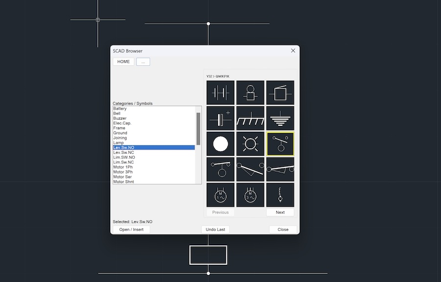
For BricsCAD, progeCAD, CMS IntelliCAD, ZWCAD, GstarCAD, and other AutoLISP-compatible DWG CAD programs, a categorized LISP Symbol Browser is also included.