P&ID Symbols Library – 300 AutoCAD symbols
Improve your engineering drawings with our comprehensive AutoCAD P&ID symbols library.
In the complex world of engineering design, accuracy and clarity of Piping and Instrumentation Diagrams (P&IDs) are paramount.
Our P&ID Symbols Library, designed for use with AutoCAD and LT, provides a comprehensive collection of over 300 crafted symbols categorized into a pulldown system.
Note: A P&ID AutoCAD library for Mac OSX is also available. (see P&ID for AutoCAD Mac).
- The library now conforms to the ANSI/ISA Standard standard
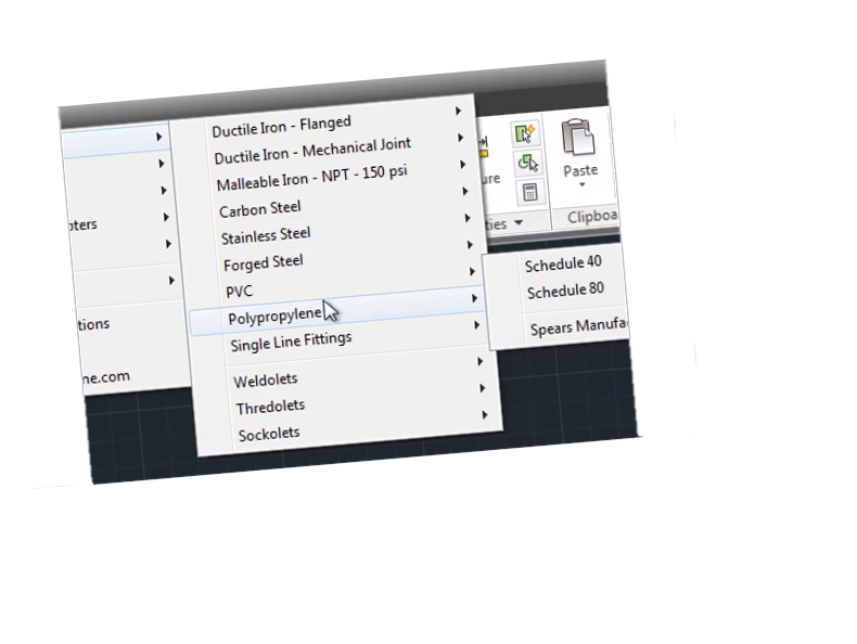
- P&ID AutoCAD symbols are accessed using a pull-down menu
- Just pick symbols and rotate in the drawing
- Installs easily into AutoCAD and AutoCAD LT
- We’ve also added ANSI drawing borders sizes A through F
- These symbols are drawn to work with a 1/16″ grid
- Full instructions are included
- 30-day money-back guarantee
This set of P&ID symbols will help you create accurate and well-defined drawings. The library includes a complete library of PID symbols, PID diagram symbols, PID valve symbols, and PID instrumentation symbols, all adhering to rigorous standards.

Understanding P&IDs and Their Importance
P&IDs are essential in engineering projects and provide a graphical representation of a process system.
P&IDs allow engineers to show how different process components are connected and how they interact.
These types of drawings help installers and plant designers understand and troubleshoot problems. P&IDs are also used to ensure that safety and regulatory requirements are met.
When labeling these symbols, AutoCAD sometimes utilizes attributes to populate information about each symbol. Attributes in AutoCAD are a way to store additional information within a block (a reusable symbol), such as identification lettering and unique tag numbers.
Here are some key advantages of this P&ID symbol library:
This library is configured into the AutoCAD menu bar for easy access (if you using the Mac version a content palette will also become available). There’s no need to browse through folders every time you need to insert a symbol.
Just select the symbol from the menu and click on “OK”.
Simply insert the symbol in your layout and rotate to the desired position. If the symbol is dynamic just click on it to access its dynamic features.
This P&ID library is suitable for various sectors; this library encompasses PID valve symbols to PID instrumentation symbols, ensures precision in P&IDs, streamlines design processes, and improves team communication.
– Consistency and accuracy: A standardized library of symbols ensures that all P&IDs are created using the same symbols, reducing the risk of errors
– Time and effort savings: This library comes with pre-built thumbnails that can save time and effort when locating P&IDs.
– Improved collaboration: Access to a comprehensive library of P&ID symbols can make it easier to communicate and collaborate with others in the industry using the same symbols.
– Enhanced professionalism: Using a standardized set of symbols can enhance the professional look and feel of P&IDs, which can be important for regulatory compliance and client satisfaction.
– Increased productivity: A library of P&ID symbols can help streamline the design process, allowing engineers and designers to focus on other aspects of the project and complete their work more quickly.
As a bonus save even more on this P&ID library! – use coupon code scad10off after clicking buy and then click the “add a coupon” link in your basket. But hurry, this offer expires very soon!
Details about the P&ID symbols
Each symbol is drawn to 1:1 scale on layer zero with “bylayer” attributes. Once inserted, simply rotate the symbol into position and it will take on the characteristics of your current layer settings.
Valve and instrument symbols also contain built-in attributes. You’ll be prompted in the command line to input the information, or just leave it blank.
What’s inside the P&ID AutoCAD Symbol Library?
The AutoCAD Block Library now ships with a total of 335 P&ID drawings which follows the ANSI/ISA Standard
The P&ID symbols are grouped in the following categories:
Process and Signal Line Types
No need to create your line types. Simply select the line type you need from the menu, then pick your start and end points. You control the look of the lines by setting AutoCAD’s LTS (line type scale) variable to the desired setting.
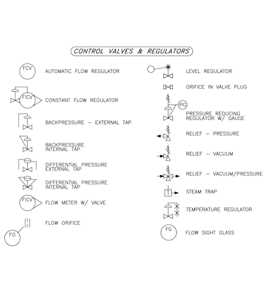
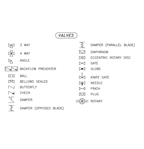
Valves
In our library, you’ll find a wide variety of valves to choose from, including ball valves, gate valves, globe valves, butterfly valves, and more.
Valve operators
You’ll find a wide range of components in our library, including solenoids, diaphragms, cylinders, motors and whatever you need to draw your schematic.
Flow elements
The library houses an impressive range of equipment, from Flow meters and rotameters to spectacle blinds just to name a few.
Pumps & Blowers
You’ll also find an impressive collection of diaphragm, centrifugal, and progressive cavity pumps, amongst others.
Tanks
We offer a variety of options, including horizontal tanks, vertical tanks, cone bottom tanks, and so much more.
Piping
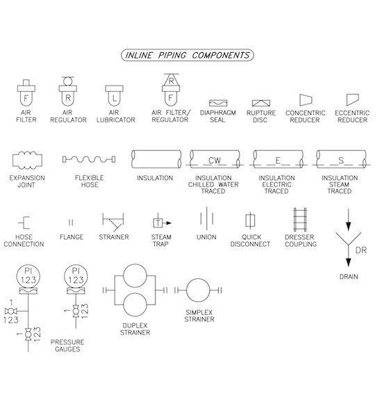
If you’re looking for P&ID piping symbols you’re at the right place! We offer a variety of blocks to choose from, like filters, pressure indicators, regulator lubricators, and even expansion joints.
Equipment
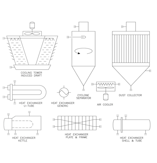
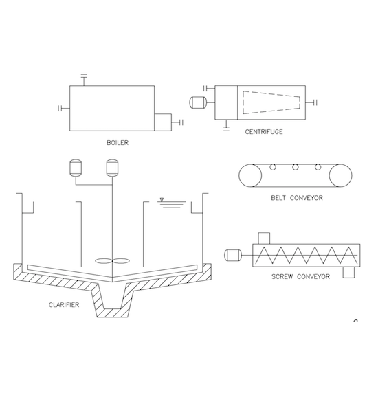
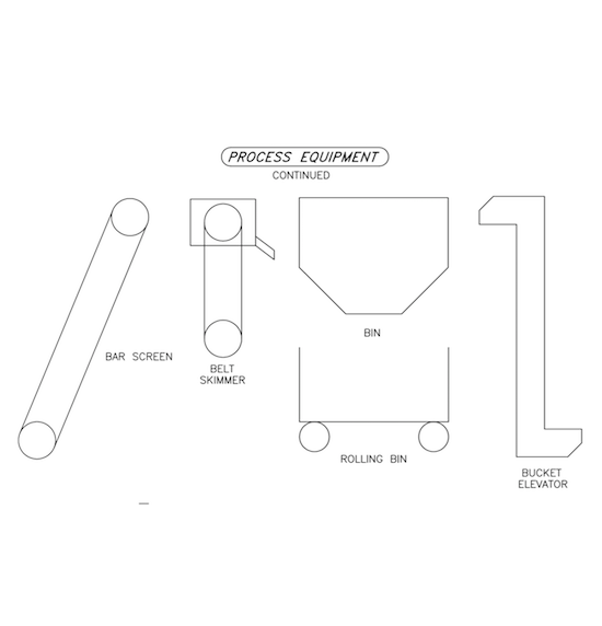
Looking for P&ID equipment? Check out our selection of bins, clarifiers, and cooling towers just to name a few.
Instrumentation & Electrical
The library is a valuable collection of instruments and electrical symbology required for creating a P&ID drawing.
Annotation
The library contains flow arrows and a revision triangle (attributes included).
To try out this P&ID AutoCAD Library please see the button at top right of this page.
If you’re not satisfied with your purchase, return it for a full refund. We also offer both single and multiple-user licenses. Grab your copy today!
A detailed list of P&ID Symbols included:
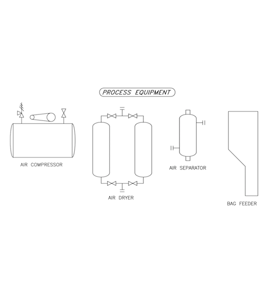
Process Equipment Diagram:
- Air Compressor
- Air Dryer
- Air Separator
- Bag Feeder
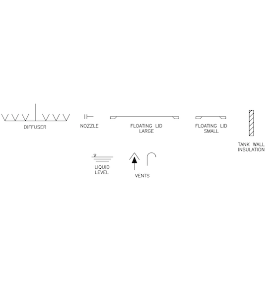
Diagram With Various Equipment Pieces:
- Diffuser
- Nozzle
- Floating Lid Large
- Floating Lid Small
- Tank Wall Insulation
- Liquid Level
- Vents
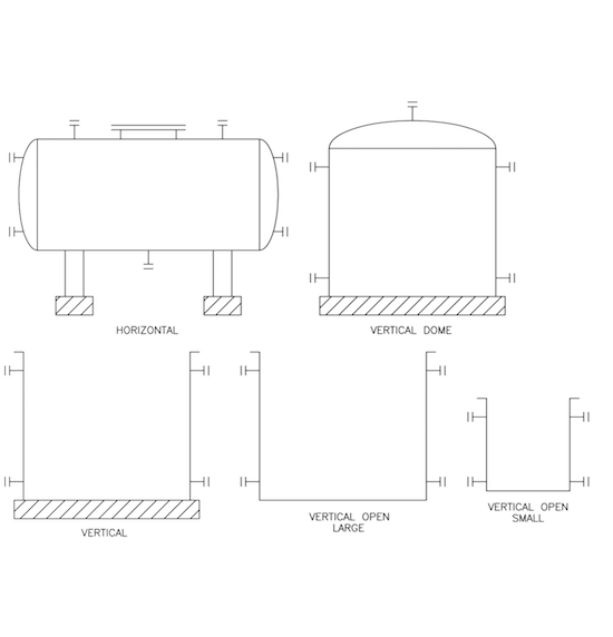
Tank Types:
- Horizontal
- Vertical
- Vertical Dome
- Vertical Open Large
- Vertical Open Small
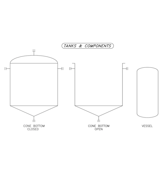
Tanks & Components Diagram:
- Cone Bottom Closed
- Cone Bottom Open
- Vessel
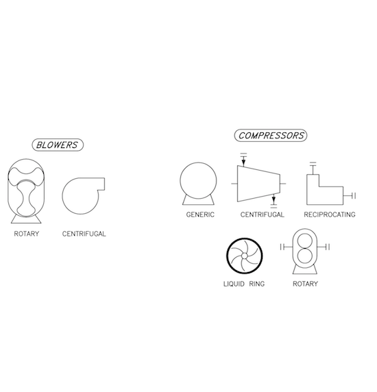
Blowers And Compressors Diagram:
- Blowers:
- Rotary
- Centrifugal
- Compressors:
- Generic
- Centrifugal
- Reciprocating
- Liquid Ring
- Rotary
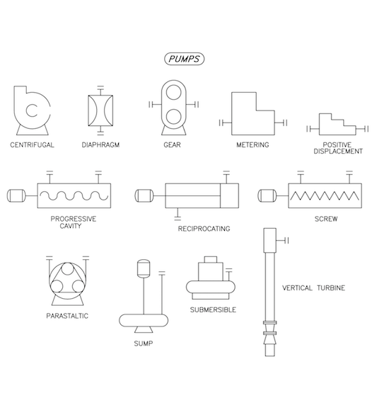
Pumps Diagram:
- Centrifugal
- Diaphragm
- Gear
- Metering
- Positive Displacement
- Progressive Cavity
- Reciprocating
- Screw
- Peristaltic
- Sump
- Vertical Turbine
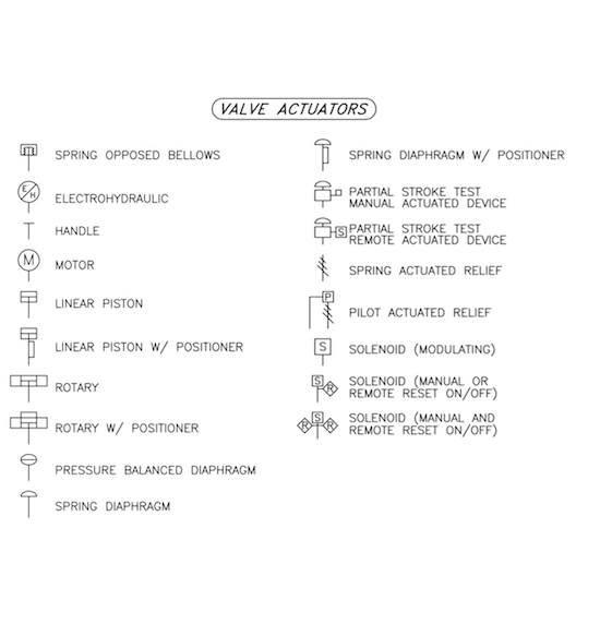
Valve Actuators Diagram:
- Spring Opposed Bellows
- Electrohydraulic
- Handle
- Motor
- Linear Piston
- Linear Piston W/ Positioner
- Rotary
- Rotary W/ Positioner
- Pressure Balanced Diaphragm
- Spring Diaphragm
- Spring Diaphragm W/ Positioner
- Partial Stroke Test Manual Actuated Device
- Partial Stroke Test Remote Actuated Device
- Spring Actuated Relief
- Pilot Actuated Relief
- Solenoid (Modulating)
- Solenoid (Manual Or Remote Reset On/Off)
- Solenoid (Manual And Remote Reset On/Off)
Valves Diagram:
- 3 Way
- 4 Way
- Angle
- Backflow Preventer
- Ball
- Bellows Sealed
- Butterfly
- Check
- Damper
- Damper (Opposed Blade)
- Damper (Parallel Blade)
- Diaphragm
- Eccentric Rotary Disc
- Gate
- Globe
- Knife Gate
- Needle
- Pinch
- Plug
- Rotary
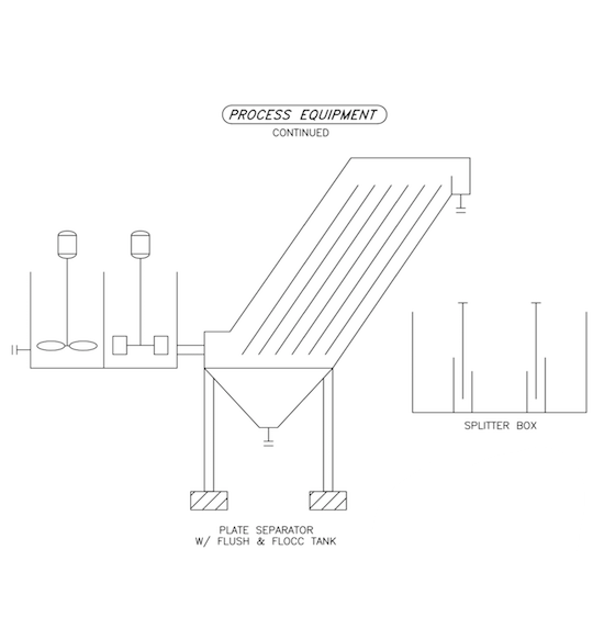
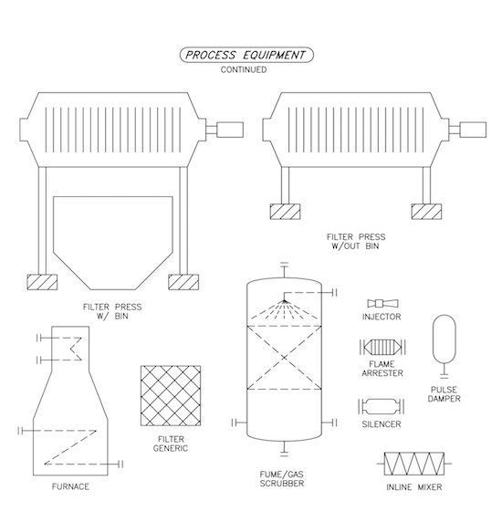
Process Equipment Continued:
- Filter Press W/ Bin
- Filter Press W/Out Bin
- Furnace
- Filter Generic
- Fume/Gas Scrubber
- Injector
- Flame Arrester
- Pulse Damper
- Silencer
- Inline Mixer
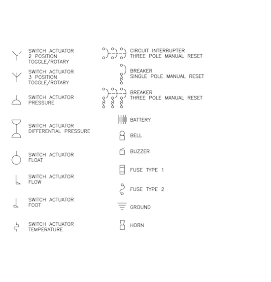
Electrical Schematic 1:
- Switch Actuator 2 Position Toggle/Rotary
- Switch Actuator 3 Position Toggle/Rotary
- Switch Actuator Pressure
- Switch Actuator Differential Pressure
- Switch Actuator Float
- Switch Actuator Flow
- Switch Actuator Foot
- Switch Actuator Temperature
- Circuit Interrupter Three Pole Manual Reset
- Breaker Single Pole Manual Reset
- Breaker Three Pole Manual Reset
- Battery
- Bell
- Buzzer
- Fuse Type 1
- Fuse Type 2
- Ground
- Horn
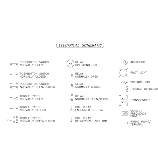
Electrical Schematic 2:
- Pushbutton Switch Normally Open
- Pushbutton Switch Normally Closed
- Pushbutton Switch Normally Open/Closed
- Toggle Switch Normally Open
- Toggle Switch Normally Closed
- Toggle Switch Normally Open/Closed
- Relay Operating Coil
- Relay Normally Open
- Relay Normally Closed
- Relay Normally Open/Closed
- Coil Relay Energized Set Time
- Coil Relay Deenergized Set Time
- Interlock
- Pilot Light
- Solenoid Coil
- Thermal Overload
- Transformer
- Variable Frequency Drive
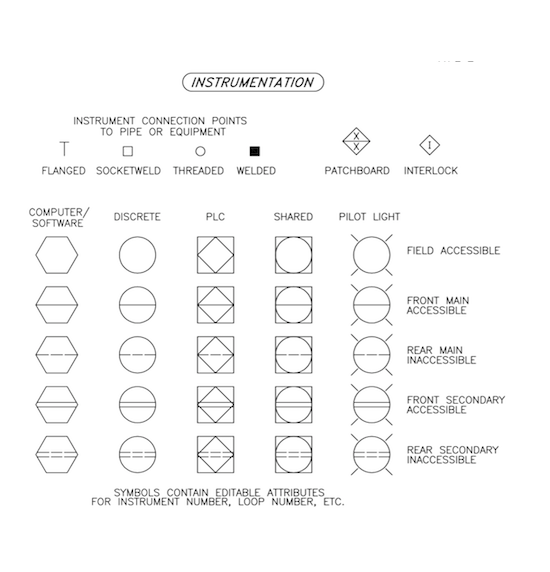
Instrumentation:
- Instrument Connection Points To Pipe Or Equipment
- Flanged
- Socketweld
- Threaded
- Welded
- Patchboard
- Interlock
- Computer/Software
- Discrete
- Plc
- Shared
- Pilot Light
- Field Accessible
- Front Main Accessible
- Rear Main Inaccessible
- Front Secondary Accessible
- Rear Secondary Inaccessible
Inline Piping Components:
- Air Filter
- Air Regulator
- Air Lubricator
- Air Filter/Regulator
- Diaphragm Seal
- Rupture Disc
- Concentric Reducer
- Eccentric Reducer
- Expansion Joint
- Flexible Hose
- Insulation
- Insulation Chilled Water Traced
- Insulation Electric Traced
- Insulation Steam Traced
- Hose Connection
- Flange
- Strainer
- Steam Trap
- Union
- Quick Disconnect
- Dresser Coupling
- Drain
- Pressure Gauges
- Duplex Strainer
- Simplex Strainer
Diffuser And Nozzle Diagram:
- Diffuser
- Nozzle
- Floating Lid Large
- Floating Lid Small
- Tank Wall Insulation
- Liquid Level
- Vents
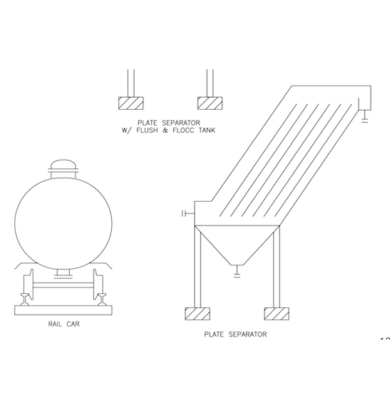
Process Equipment Additional Diagrams:
- Plate Separator W/ Flush & Floc Tank
- Rail Car
- Plate Separator
- Splitter Box
Process Equipment Additional Diagrams 2:
- Plate Separator W/ Flush & Floc Tank
- Splitter Box
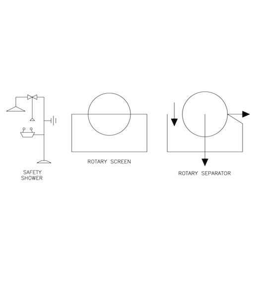
Safety And Separation Equipment:
- Safety Shower
- Rotary Screen
- Rotary Separator

