2D Piping Symbols Library for AutoCAD
2D Piping Symbols
Streamline Your Workflow with Easy-to-Use Symbols
Accuracy and precision are crucial in engineering drawings, especially when working with piping and instrumentation diagrams. This 2D Symbols Library for AutoCAD significantly enhances the creation of detailed piping schematics, allowing for faster and more precise output. Its user-friendly interface lets users quickly insert piping symbols using straightforward menus and dialog boxes. This ease of use is particularly beneficial for professionals who need to rapidly develop piping plans, sections, and elevations without sacrificing quality.
Utilizing standardized piping symbols ensures consistency and clarity in communication among team members and stakeholders during complex engineering projects. This library adheres to industry standards, ensuring each symbol is drawn accurately.
The 2D Piping Symbols Library includes essential piping symbols for AutoCAD and AutoCAD LT, supporting versions from 2006 through 2025. With over 10,000 symbols, this design tool allows easy access through a convenient pulldown menu. The library is meticulously organized into categories for quick retrieval of various piping symbols, with multiple symbols available to represent a single fitting, depending on the installation method, such as butt weld or threaded connections.
- Insert symbols using pulldown menus and dialog boxes.
- Quickly generate piping plans, sections, and elevations.
- The red plus symbol indicates the base or insertion point of the block.
- Insert, rotate if needed, and you’re done.
Need 3D piping symbols? We’ve got those too! High-quality 3D pipe symbols have similar features, including easy installation and quick menu access.
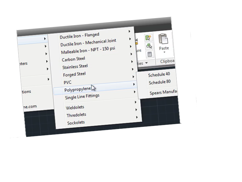
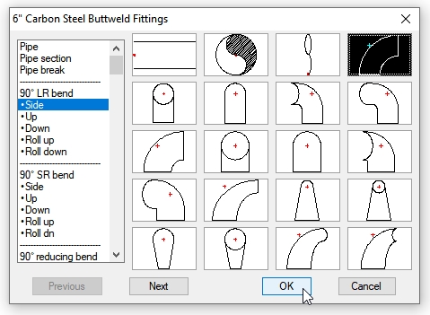
Thumbnails of Interface, Ductile Iron and Buttweld Fittings
The image above shows how easy it is to access menus and pipe sizes.
What Are Piping Schematics?
Piping symbols are essential in various industries. They provide detailed drawings showing various piping layouts, ensuring that every component is accurately represented and easily understood by engineers, welders, and fabricators alike.
Understanding the Basics of Pipe Drawings
These pipe symbols offer a more detailed representation. This level of detail is invaluable for process engineers, designers, and operators, as it helps them understand the intricate workings of the plant processes and equipment layout.
The 2D Piping Symbols Library for AutoCAD is more than just a collection of symbols; it’s a powerful tool that improves the overall drawing process. Its user-friendliness, adherence to standards, and immediate availability make it a must-have for any engineer or designer looking to streamline their workflow and enhance the accuracy of their pipe drawings.
This library also includes specific Weldolets, Thredolets, Sockolets symbols and expansion joints. Implementing these symbols in your project ensures your designs are efficient and meet the highest standards of quality and precision.
Save Time with This Piping Block Library
Imagine the time saved by having over 10,000 piping symbols ready to use, each organized into categories for easy access. This extensive collection includes a variety of piping fittings, valves, and other essential components; you avoid the need to draw each symbol from scratch, allowing you to focus on other important parts of your project.
Each symbol is drawn to a 1:1 scale on layer zero with “byblock” attributes. Once inserted, simply rotate the symbol into position, which will adapt to your current layer settings.
Also, Consider this: There are 10,841 piping symbols in this library. A CAD operator making $18 per hour can create one symbol every two minutes, nonstop … or 30 symbols per hour.
We divide our 10,841 piping symbols by 30 symbols per hour, resulting in 361 work hours. At $18 per hour, your CAD operator would be paid $6,498.00 to create this piping block library!
A Ready-To-Use Piping Block Library
There’s nothing to learn. Just load the library in AutoCAD and go! This top-seller is popular for a reason. The library self-installs, so there’s little to do to get started.
Note: Pipe fitting insertion points are located at the intersection of the pipe centerline. Centerlines are not included with the blocks because they are usually on a separate layer and color.
Piping Blocks Include In The Library
Piping Blocks Include In The Library
This easy-to-install Piping Library ships with 10,841 symbols in the following categories:
Piping Fittings:
Ductile Iron Flanged fittings – sizes 4″ through 48″
ANSI/AWWA C110/A21.10
Elbows – 11.25°, 22.5°, 30°, 45°, 90°
Tees – full size & reducing
45° Wyes & laterals – full size & reducing
Crosses
Reducers – concentric & eccentric
Blind flanges
Ductile Iron Mechanical Joint fittings – sizes 4″ through 48″
ANSI/AWWA C110/A21.10
Elbows – 11.25°, 22.5°, 30°, 45°, 90°
Tees – full size & reducing
45° Wyes & laterals – full size & reducing
Crosses – full size & reducing
Reducers – concentric & eccentric
Carbon Steel Buttweld fittings – sizes 1/2″ through 24″
Elbows – 90 & 45
Tees – full size & reducing
Reducers – concentric & eccentric
Pipe cap
Flanges – 150# to 2500# – weld neck, threaded, slip-on, lap joint, blind – Includes bolt holes & raised faces
PVC socket fittings – sizes 3/8″ through 24″
Schedule 40 & 80
Elbows – 11.25, 22.5, 30, 45, 90
Tees – full size & reducing
45 Wyes & laterals – full size & reducing
Crosses – full size & reducing
Reducers – concentric
Caps
Unions
Couplings
Flanges
Forged Steel Threaded fittings – sizes 1/8″ through 4″
3000# & 6000# – ANSI/ASME B16.11
Elbows – 45, 90
Tees
45 Laterals
Crosses
Caps
Unions
Couplings
Forged Steel Socketweld fittings – sizes 1/8″ through 4″
3000# & 6000# – ANSI/ASME B16.11
Elbows – 45, 90Tees
45 Laterals
Crosses
Caps
Unions
Couplings
Weldolets, Thredolets, Sockolets
Views: side & end
Weights: standard, extra strong, double extra strong, 3000# & 6000#
Weldolets: run sizes 1/2″ through 24″ outlet sizes 1/2″ through 24″
Thredolets: run sizes 1/2″ through 36″ outlet sizes 1/8″ through 4″
Sockolets: run sizes 1/2″ through 36″ outlet sizes 1/8″ through 4″
Valves:
Angle valves – sizes 1/2″ through 12″
classes 125, 300 & 600
Ball valves – sizes 1/2″ through 12″
classes 125, 150 & 300
150psi for PVC
Butterfly valves – sizes 1/2″ through 36″
class 150
150psi for PVC
Check valves – sizes 1/2″ through 24″
classes 125, 150, 300 & 600
150psi for PVC
Diaphragm valves – sizes 1/2″ through 10″
150psi PVC only
Gate valves – sizes 1/2″ through 30″
classes 125, 150, 300 & 600
150psi for PVC
Globe valves – sizes 1/2″ through 14″
classes 125, 150, 300 & 600
150psi for PVC
Plug valves – sizes 1/2″ through 20″
classes 150 & 300
Expansion joints:
Manufacturer: Flexicraft
Styles: Rubber arch, Type N metal, Type NLC metal
Rubber: 1,2 & 3 arch; concentric & eccentric reducing; 150# flanges – sizes 1″ to 48″
Metal: 50#, 150# & 300# flanged and buttweld ends – sizes 2″ through 36″
Repair couplings and adapters:
Manufacturer: Dresser Couplings
Style 38 coupling (for steel pipe)
sizes: 1/2″ through 48″
Style 138 coupling (for ductile iron pipe)
sizes: 4″ through 16″
Style 128-W flanged adapter (for steel pipe)
sizes: 2″ through 24″
Style 128-W flanged adapter (for ductile iron pipe)
sizes: 4″ through 24″
Pipe insulation symbols:
Pipe sizes: 1/2″ through 48″
Insulation thickness: 1″ through 4″ Pipe insulation symbol shown in white.
(Pipe & centerline not part of the symbol, shown for reference only)
If you’re unsatisfied with your purchase, you can return it for a full refund. We offer single- and multi-user licenses. Get your copy today!
Try all our piping software – all 4 packages in one menu or individually.
This 2D Piping Symbols Library is available immediately after purchase, so you can add it to your AutoCAD setup immediately. This immediate access means you can start improving your inputs without delay, reducing downtime and boosting productivity.
Whether you’re working on a small project or a large industrial design, having a wide range of piping symbols at your fingertips can greatly enhance your work efficiency.
Other related symbols
Libraries below are available in 4 pack library (demo trial) we offer (these modules are not found in this individual 2D Piping library):
- 3D Piping – provides real-life sized pipe drawings of various fittings, similar to those in this library but rendered in 3D. This tool enhances your engineering system’s design by allowing a more comprehensive 3D visualization of connected pipe layouts. Experience the 4-pack demo to explore this library further.
- The Piping and Instrumentation Diagram (P&ID symbols) feature detailed schematics that represent process equipment alongside control instrumentation. These diagrams include flow elements such as switches, nozzles, and orifices. The library is rich with instrumentation symbols, equipment symbols, and various types of industrial equipment, including vessels, valves, pumps, compressors, and motors.
- Isometric Piping Symbols – adhere to industry standard symbols. In an isometric drawing, you can efficiently illustrate the operational process by connecting pipes and fittings using single lines. This allows for a quick development of a piping system layout, clearly indicating flow direction, control valves, blowers, and other essential equipment.
- The demo trial includes our 4-pack demo, which encompasses all the piping fittings listed. Although some blocks cannot be inserted in the demo, a selection in each category is available for you to try before purchasing. For 2D-only drafting and LT users, a 3-pack is also available.\
Download a demo of the Piping Library for AutoCAD (near the buy button). (note: download includes 2D piping symbols and an option to download plus other related piping libraries mentioned above).
Free Install Offer – if you need help we offer a remote install to your computer, small app provided. Call us at 877-933-3929 for more.
Tired of finding the piping symbol you need then finally having to draw it from scratch every time? With the Piping Symbols Library it is at your fingertips every time you load AutoCAD.


